Wavelength, Physical Length and Relative Permittivity
CommentsCreated Saturday 08 May 2021
This page will explain some of the relationships between physical length and relative permittivity and especially some techniques to determine these parameters while taking advantage of half-wavelength structures. The ultimate goal is to use these values to find the following unknowns:
- Find an unknown relative permittivity with a cable of known length
- Find an unknown cable length with a cable of known permittivity
Video Tutorial
The contents of this page are described in the following video:
A Note about Velocity Factor
The Velocity Factor (VF) is a property of transmission lines, specifically used with coaxial cables. Since any dielectric permittivity greater than 1 (air/vacuum) will have the effect of slowing the phase velocity of a wave, the VF is given as a percentage representing that reduced phase velocity.

Relationship between Er and Wavelength
We want to be able to relate the permittivity and the physical length of the line. To begin with, we take two equations from Page 7 of Pozar's Microwave Engineering [1].
(1) 
(2) 
The first equation states that the phase velocity is equal to frequency times wavelength. The second relates the phase velocity to the dielectric constant using the speed of light. Putting them together gives us either:
(3) 
or:
(4) 
Adding in Physical Length
We can use transmission line properties to use these equations to our advantage. If we have a half-wavelength line, the properties would be as follows:
(5) 
If you have some known properties and a half-wavelength line, it is possible to determine other parameters. For example, if you know the relative permittivity and know the frequency of a half-wavelength line, it's possible to put Equations (4) and (5) together to determine the physical length. Similarly, if you know the physical length and frequency of half-wavelength, you can determine the effective relative permittivity. This could come in handy for evaluating unknown cable types.
Using Technique in Practice
Based on the equations above, it is necessary to determine the half-wavelength frequency of the cable/transmission line in question. One of the quickest methods is to simply take a one-port VNA measurement of one end of the cable with the other end open. This would give a wrapped phase plot as shown below:
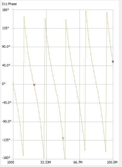
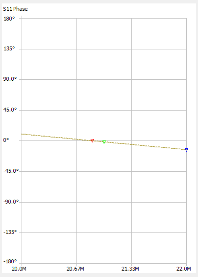
The first point where the phase crosses zero is the frequency at which the line's physical length is half-lambda. We can zoom in on that point for more accuracy. In this example, the phase plot crosses zero at exactly 20.86 MHz.
One nice thing about this method is that it works even when the cable's characteristic impedance does not match the port impedance of the VNA. In that case, the phase will simply be non-linear but will still cross zero at the correct location as shown in the two plots above.
A downside of this method is that longer cables require lower frequency measurement. For a PTFE dielectric (Dk=2) if your VNA goes down to 1 MHz, you could measure a cable length of about 212m (700ft) or so. In addition to this, you must be careful with long lines that the first zero-crossing isn't masked by large sample spacing in the S-Parameter measurement or simulation. For example, if you're looking at a point under 1 MHz, and you sample a range from 0 to 1 GHz linearly with 101 points, each point is 10 MHz spaced apart and you'll never see the intended zero-crossing. Some intuition must be used to determine an appropriate frequency sweep setting.
Example 1: Determine Unknown εr
Assume that you have a cable of known length (1m in this example) but need to know the velocity factor. Taking the phase(S11) measurement gives the following plot:
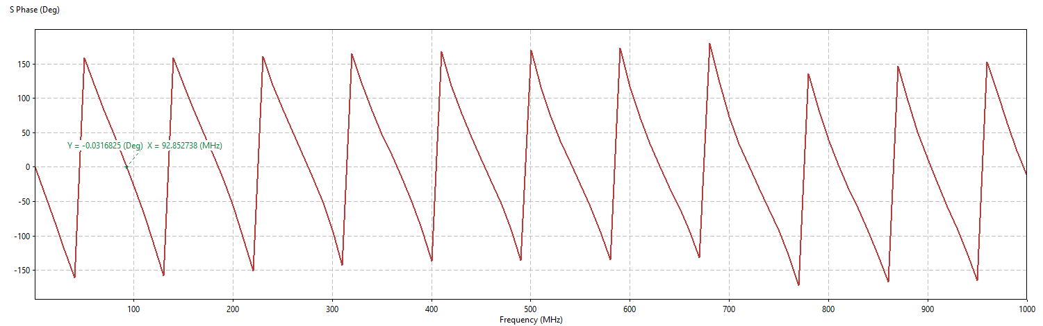
The first zero-crossing on the phase plot is at 92.853 MHz. Using Equation (3) above, the resultant relative permittivity is 2.61, indicating a velocity factor of 62%.
Example 2: Determine Cable Length
In this case, assume you have a cable coiled up which is listed as T10 Drop Cable (75Ω CATV coax). This cable has a VF of 85%, meaning εr is 1.38. You take a phase measurement of the cable and see the following result:
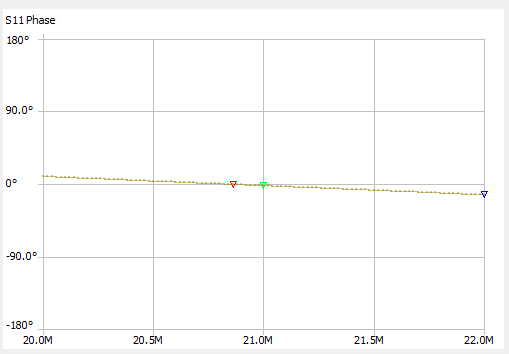
The first zero-crossing of the phase is at 21.86 MHz. Using Equation (4) above, the resultant lambda is 12.24. Since the cable length is half of this, the cable length is approximately 6.12 m (20.08 ft).
Final Notes
- Why can't we just use the TDR function to determine length, or the specific features in the NanoVNA?
- Of course this is possible if you have equipment with this capability. Often, especially with the NanoVNA, it's much quicker to take a single S11 measurement than it is to configure the velocity factor and other settings for a length measurement. This is just another tool in the toolbox
References
[1] Microwave Engineering, David Pozar
Contact Stephen with any questions: Stephen@ShieldDigitalDesign.com
© Shield Digital Design