Effect of Loss Tangent on Characteristic Impedance
CommentsCreated Thursday 12 October 2023
All simulation models contained on this page are available for download in a Simbeor project linked here.
The dielectric model type must be changed to see the variations explored.
This page is based on a question on the SI-List:
Date: Wed, 11 Oct 2023 16:14:34 -0700
Subject: [SI-LIST] reflection coefficient dependence on tangent loss
Hi Experts,
I wanted to get some insights about the reflection coefficient's (S11)
dependence on tangent loss.
My understanding is Dk/tangent loss doesn't affect the reflection
coefficient. Let me know what you think.
To answer it, we can use Simbeor to explore some basic transmission line structures. We know that the characteristic impedance can be described with the RLGC parameters as follows:

In this case, we reference Pozar's Microwave Engineering, Equation 2.7.
Since the loss tangent impacts dielectric loss (the G/conductance term), then we would perhaps expect that characteristic impedance will go down with a higher loss tangent. Using Simbeor, we can configure a basic stripline structure.
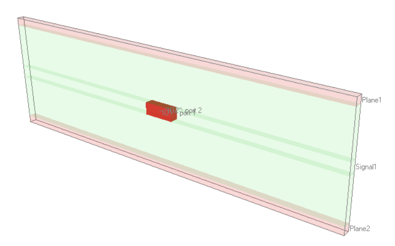
We'll use a standard Dk of 4.2 and vary the loss tangent from 0 (lossless), to 0.02 (typical FR-4) to 0.05 (quite high). If we configure the tool to use a flat/non-causal dielectric model, then the system behaves exactly as we expect. The figure below shows characteristic impedance and RLGC values. The Z0 varies only slightly, from 49.527Ω with LT=0, to 49.497Ω with LT=0.05. This exactly validates our expectation where Z0 is reduced with higher loss tangent. Note that R, L and C are all totally unchanged for the three variations. The conductance, G, is increased with higher loss tangent. Unfortunately, a flat, non-causal dielectric model should not be used in wideband simulations for signal integrity.
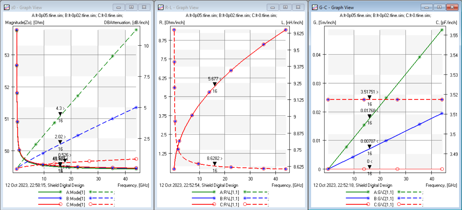
Green: LT = 0.05, Blue: LT = 0.02, Red: LT = 0.0
- Left: Characteristic impedance (left axis) and attenuation (right axis)
- Middle: R and L (left/right axes respectively)
- Right: G and C (left/right axes respectively)
We would want to use a causal, frequency dependent dielectric model for our simulations. In this case, we might select the Djordjevic-Sarkar model (also known as either Wideband Debye or Infinite Pole Debye). This is discussed in great depth in Sections 6.3 and 6.4 of "Advanced Signal Integrity for High-Speed Digital Designs" by Stephen Hall and Howard Heck. Specifically, "the real part of the permittivity (ε′) is a function of the imaginary part (ε′′), and vice versa" (from Pg. 270 of this book).

Recall that the loss tangent is related to the real and imaginary parts of the permittivity by:
Based on these definitions, we would expect to see some change in both C and G.
The plots below show the same characteristics, but with a Wideband Debye, causal, dielectric model. Here we must point out that while all of the markers are showing behavior at 16 GHz, the dielectric properties were specified at 1 GHz. The plots following show the characteristic impedance and the capacitance zoomed into the 1 GHz point. At exactly that location, Z0 does follow the same pattern (higher loss tangent results in lower Z0). We see that capacitance at this point matches up exactly for all loss tangent variations. As we go up in frequency, there is a significant difference in characteristic impedance depending on only a change in the loss tangent. The takeaway here is that we must be extremely aware of not only the material properties, but the methods used to model them in simulation.
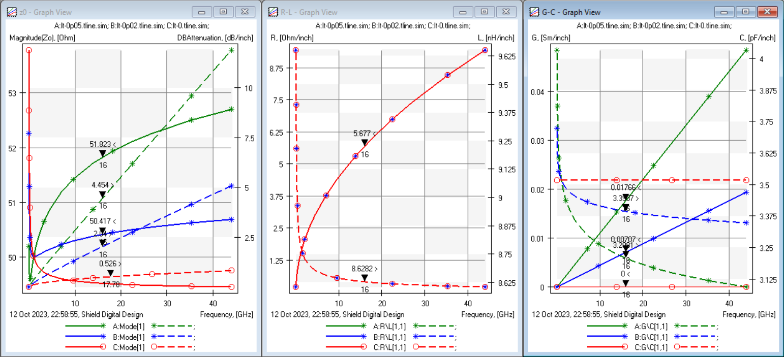
Green: LT = 0.05, Blue: LT = 0.02, Red: LT = 0.0
- Left: Characteristic impedance (left axis) and attenuation (right axis)
- Middle: R and L (left/right axes respectively)
- Right: G and C (left/right axes respectively)
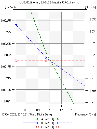
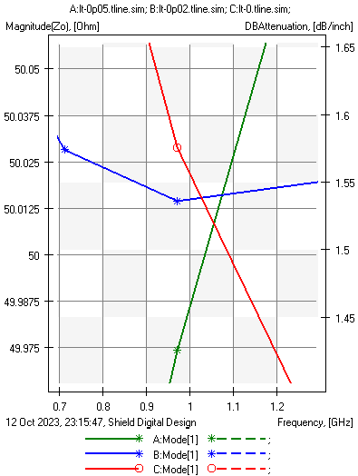
Green: LT = 0.05, Blue: LT = 0.02, Red: LT = 0.0
- Left: Capacitance (C), (right axis)
- Right: Characteristic impedance (left axis)
Interestingly, nothing here yet answers the initial question about return loss or reflection coefficient.The plots below show that return loss is very high for the LT=0.05 case regardless of the dielectric model used. Similarly, return loss matches well for LT=0 and LT=0.02 above ~15 GHz, though at low frequencies (under 5 GHz) there's significant difference.
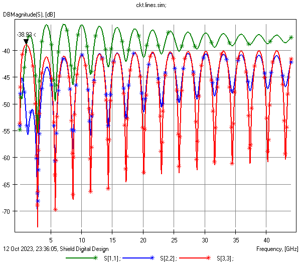
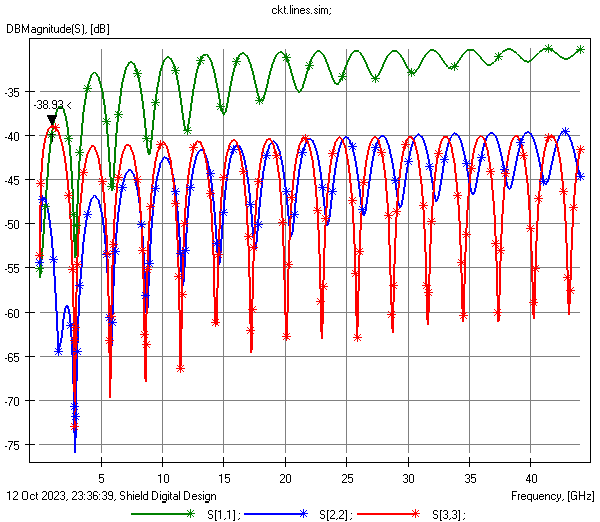
Green: LT = 0.05, Blue: LT = 0.02, Red: LT = 0.0
- Left: Return loss of a 1" trace with a flat, non-causal dielectric model
- Right: Return loss of a 1" trace with a causal Wideband Debye dielectric model
References
This page makes extensive reference to the following:
- "Advanced Signal Integrity for High-Speed Digital Designs" by Stephen Hall and Howard Heck
- "Microwave Engineering" by David Pozar
Contact Stephen with any questions: Stephen@ShieldDigitalDesign.com
© Shield Digital Design
