W-Element Model
CommentsUpdated Tuesday 06 June 2023
A W-Element model is a simplified model of one or many transmission lines used in circuit simulation. It is essentially an RLGC matrix with a line length included, thus it contains all of the transmission and material parameters such as skin-effect/roughness losses, dielectric losses, characteristic impedance and mutual coupling. It is typically created with a field solver, and then used within a schematic-based circuit simulation environment.
The RLGC telegrapher's equations are valid for TEM transmission lines. Although microstrip lines are not purely TEM, the error is minimal and RLGC models are still used. This is referred to as quasi-TEM.
W-element models can be used in many simulation tools such as Cadence Sigrity, Ansys Electronics Desktop and Keysight ADS. They can be generated in these tools or with the open-source TNT/MMTL Field Solver (though TNT is limited to lossless lines).
Origins
In the section of the HSPICE user manual describing linear elements, there are U-, W-, and S-elements available. The U-element is a lumped transmission line given with a geometric input. he U-element is less optimal and is limited to five transmission lines in a single model. The U-element can cause oscillations as a result of the lossy approximation. The W-element is a far better alternative which avoids this spurious ringing.
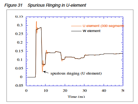
(Figure from the HSPICE Signal Integrity User Guide.)
The W-element (so-called because it is instantiated as Wxxxx in HSPICE) uses numerical values for the transmission line per-unit-length properties (also known as P.U.L. properties). These are more commonly known as RLGC for resistance, inductance, conductance and capacitance per meter. The definition of this kind of model means that one can simulate transmission lines with varying length very easily. Compare this to typical post-layout simulation flows where an S-parameter model is extracted: the S-parameter model is a high fidelity reproduction of expected circuit behavior but it is not easily modified for different lengths. The W-element model really shines during pre-layout simulation activities where the engineer is determining which constraints need to be applied to the design - specifically: what transmission line lengths are acceptable and what crosstalk coupling values are allowed. The accuracy in W-elements comes from the ability to model behavior with differing RLGC values per frequency. This allows for realistic conductor loss (which increases with frequency due to skin effect) as well as dielectric loss which is a frequency dependent value as well.
Simulation
Creating W-Element Models
While of course a W-element can be called from SPICE if your particular variant supports it, there are also other tools which can generate the needed RLGC models.
TNT/MMTL
There are more details at TNT-MMTL Field Solver. The most important limitation is the fact that TNT cannot include dielectric loss in its RLGC output. While TNT is wonderful for quick impedance calculations, it should be avoided if dielectric loss is critical.
Simbeor
Simbeor is arguably the best "bang for your buck" field solver on the market today. While it has extensive 3D capabilities, it is also excellent for 2D transmission line solutions. While it is possible to generate RGLC models with any of the three available field solvers (SFS, 3DML and 3DTF), most often the SFS solver will be used. The following instructions will show how to generate this RLGC model for SPICE simulation.
- Create the circuit
- Often, using the TLine wizard is the fastest way to do this
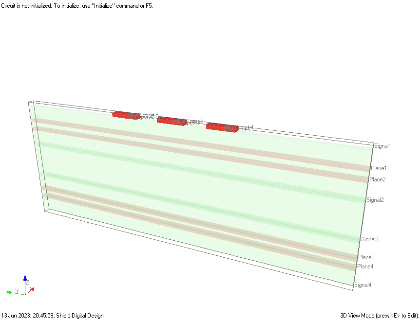
- It is possible to create one from scratch, simply place the transmission line with both start and end at location 0.
- Add as many segments as needed to properly model the cross-section. In the image below, three lines are included.
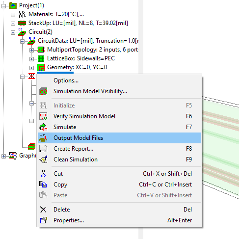
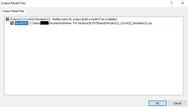
- After simulating, right-click the simulation object and choose Output Model Files. Check the SpiceRLGC and press OK.
- The SPICE model is exported to the results directory. A snippet is shown below.
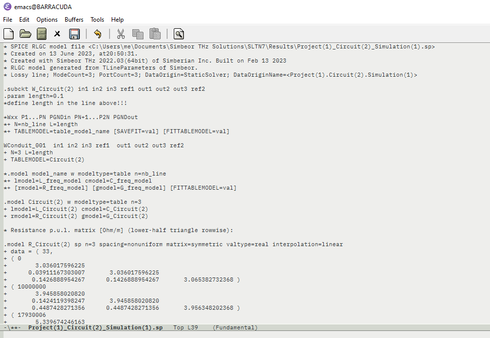
- An attached copy of this model is included here as well:
- Note that the user must modify the length parameter in this model.
Simulating with W-Element Models
Using a big-name SPICE simulator such as Synopsys HSPICE, Cadence Spectre, Ansys Nexxim or Keysight ADS will certainly support these W-element models. Other simulators are less likely to support this device. For example the free version of Micro-Cap does not support it.
References
[1] https://resources.pcb.cadence.com/vidyard-all-players/understanding-w-element-transmission-line-model-for-pre-layout-parallel-bus-in-systemsi
[2] D.B. Kuznetsov, E. Schutt-Aine: Optimal transient simulation of transmission lines (https://ieeexplore.ieee.org/document/486433)
[3] H-Spice SI User Guide, accessed at http://www2.ece.rochester.edu/courses/ECE222/hspice/hspice_si.pdf
[4] http://na.support.keysight.com/plts/help/WebHelp/FilePrint/RLCG_Data_Formats.htm
Backlinks:
High Speed Design Wiki:Glossary
High Speed Design Wiki:Software Tools:TNT-MMTL Field Solver
Contact Stephen with any questions: Stephen@ShieldDigitalDesign.com
© Shield Digital Design