TNT-MMTL Field Solver
CommentsTNT is an amazing open-source 2D/2.5D field solver for transmission line design. It works excellently for planar structures, but also supports circular conductors. It can even generate W-Element Models for system-level analysis. The best use-case for TNT is in validating controlled impedance geometries. The biggest downside is that it does not model dielectric losses, so the conductance parameter (G in the RLGC model) is not present thus not suitable for modeling long channels where loss is critical.
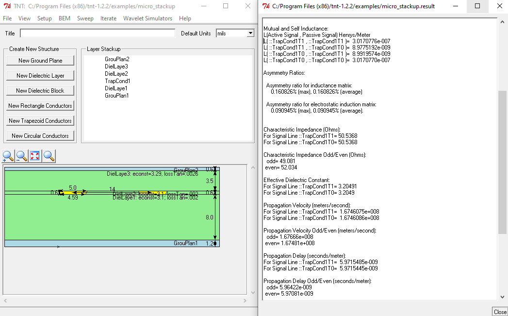
Screenshot of TNT
Downloading
Go to: http://mmtl.sourceforge.net/
Quick Details:
Etch Angle
When designing transmission lines, be sure to account for etchback as described in: +Copper Etchback
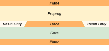
Stripline Dielectrics
Note that when a PCB is constructed, the resin from the prepreg flows between the adjacent traces. This reduces the thickness of the prepreg compared to the datasheet value and also provides a slightly different dielectric constant compared to the assumption that the Dk is identical all around the trace. (Since the resin has a slightly different Dk than the combined prepreg).
Tutorial
This tutorial will cover a couple of common use-cases for TNT:
- Microstrip trace
- Stripline trace
- Describe result parameters
- View RLGC model
Tutorial Notes
- Soldermask can be modeled with a dielectric block rather than a layer, and sometimes the impedance value will vary slightly between the two
- For coplanar lines, rather than using the "g" as specified in the documentation, use the prefix "ground" to properly reduce the matrix to a single signal
Example Files
The example files from the video can be downloaded below:
Backlinks:
High Speed Design Wiki:Software Tools
High Speed Design Wiki:Glossary:W-Element Model
Contact Stephen with any questions: Stephen@ShieldDigitalDesign.com
© Shield Digital Design